Simple Decoder Circuit Diagram
How to design of 2 to 4 line decoder circuit, truth table and applications What is a decoder? operation, types and applications Decoder & multiplexer
3 to 8 Line Decoder PLC Ladder Diagram | InstrumentationTools
Decoder circuit binary diagram truth basic decoders logic gate circuitdigest block tables using basics working not saved following draw Encoder priority circuitdigest decoder Decoder demultiplexer encoder binary iitr
Decoder circuit encoder diagram digital circuits analog signal gr next electronics
Decoder logic decodificador rangkaian equations circuitos encoder instrumentation circuito nutshell demultiplexer bcd ingressi combinational integrato usciteDecoder circuit diagram logic digital line combinational electronics Decoder diagram block line using 16 circuit binary demultiplexer multiplexer digital outputs designing following eight its octal electronicsHow to design a 4 to 16 decoder using 3 to 8 decoder.
Decoder in digital electronicsDecoder circuit seven segment 5 bit |simple schematic diagram Decoder plc ladder instrumentationtools solutionDesign 3×8 decoder and 8×3 encoder using vhdl.

12+ 4 to 2 priority encoder circuit diagram
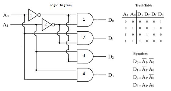
Decoder circuit diagram types gates block output operation two inputs will applications binary inverters provide which hasDecoder circuit 16 using line truth table multiplexer enable binary high segment designing only digital Binary decoders: basics, working, truth tables & circuit diagrams3 to 8 line decoder plc ladder diagram.
Decoder line diagram circuit plc instrumentationtools implement ladder problem solutionDecoder circuit line truth table decoders encoders binary input bit decode combination designing Decoder electronics digital circuit javatpoint encoders topic nextDecoder & encoder.

Decoder vhdl encoder 8x3 3x8 ckt engineersgarage
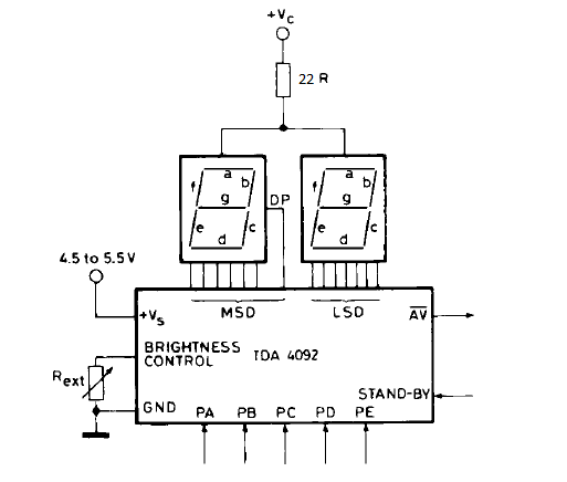
3 to 8 line decoder plc ladder diagramVirtual labs Instrumentation in a nutshell: decoderDecoder segment seven circuit bit schematic pd diagram.
.


